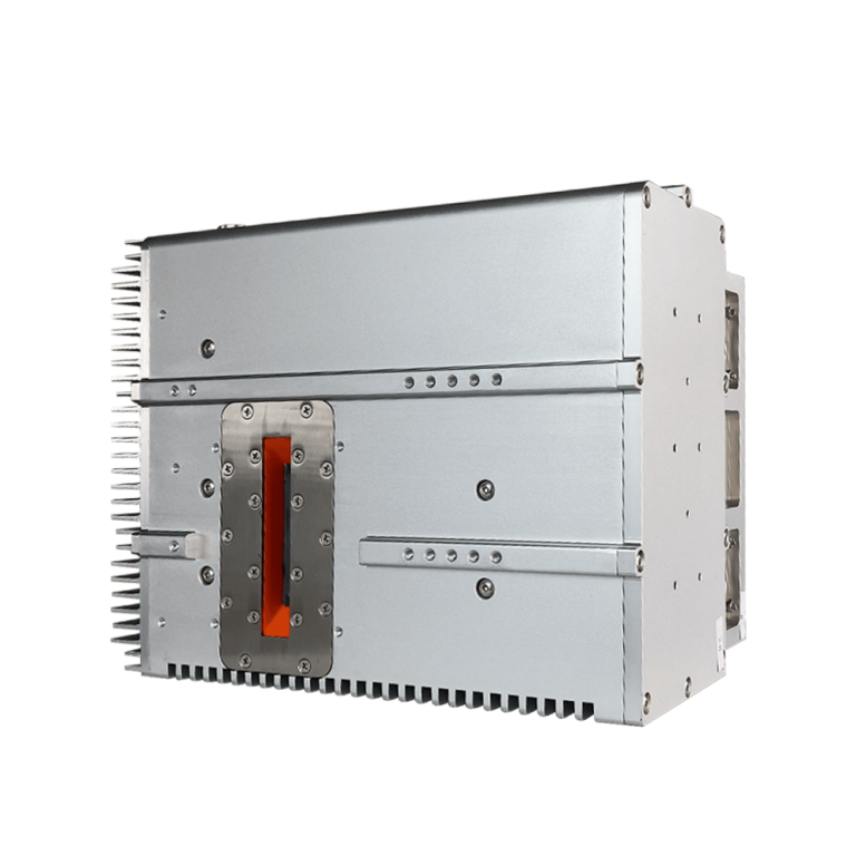
The HVC501C0 is an integrated X-ray source with built-in self-protection features, characterized by its compact structure, easy installation, and reliable operation. It delivers up to 50kV/50W output and supports continuous operation at rated power within the allowable operating temperature range. With a standard RS232 digital interface, it enables remote control, status monitoring, and firmware upgrades.
Food testing, industrial non-destructive testing, dangerous goods testing and other fields.
| Item | Specification |
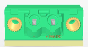
| Input voltage | 24VDC±2V%,4.2Amps |
| Output power of X ray tube | Max continuous output power 50W(50kV/1mA)) |
| Output voltage | Rated output voltage:Continuously adjustable voltage range 20kV—50kV |
| Output voltage ripple:±0.5%(peak to peak) | |
| Output voltage accuracy:±2% of voltage setting value | |
| line regulation:±0.1% | |
| load regulation:±0.1% | |
| Tube current | ated tube current:Continuously adjustable current range 0.2mA-1mA |
| Tube current accuracy:±1% mA of current setting value | |
| line regulation:±0.1% | |
| load regulation:±0.1% | |
| Rise time of output voltage | The voltage rise time is less than 0.6 seconds at maximum power, and less than 0.1 seconds when the output voltage is below 40kV. |
| Filament power supply: | input voltage:24VDC |
| filament voltage:3.5VAC | |
| Filament current:3Amps RMS | |
| preheating time:3sec | |
| Tube feature | Tube type: fixed anode, glass window, tungsten target |
| focus:0.8mm | |
| inherent filtration: 0.7mm AI | |
| radiation angle:30°cone beam | |
| target angle:15° | |
| Cooling | transformer oil, anode heatsink with fan cooling |
| Working temperatures | -10℃—35℃ |
| Storing temperature | -20℃—60℃ |
| System temperature protection | 60°C ± 3°C of Oil temperature: |
| Humidness | 98%,Non-condensation |
| Weight | 4.65kg |
| Installation direction | Installation in any direction |
| Radiation angle | 30°cone beam |
| X-ray leakage | Less than 0.5mR/hr at 5cm from the surface of the HVC501C0. |
JB1/AC~(AC Input Power Connector)
JB2/COM (DMR-9S interface definitions)
| Pin | Signal | Parameter |
| 1.4.6.7.8.9 | N/C | No connect |
| 2 | TXD | Data transmit |
| 3 | RXD | Data receive |
| 5 | GND | Signal gnd |

J3 / External Port
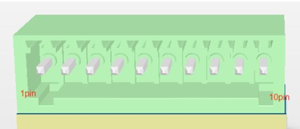
Note: Pin No.— J3 is numbered from left to right as 1pin to 10pin.
| Pin No. | Name | Description |
| 1 | Interlock In | Safety interlock switch input |
| 2 | Interlock Out | Safety interlock switch output |
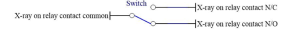
| 3 | X-ray on relay contact common | Common terminal of X-ray switch indicator relay |
| 4 | X-ray on relay contact N/C | Pin 3 and Pin 4 are connected when X-ray is on; disconnected when X-ray is off |
| 5 | X-ray on relay contact N/O | Pin 3 and Pin 5 are disconnected when X-ray is on; connected when X-ray is off |
| 6 | IP | Current monitoring output, 0~5VDC |
| 7 | EP | Voltage monitoring output, 0~5VDC |
| 8 | SGND | Ground |
| 9 | NULL | Reserved |
| 10 | NULL | Reserved |
Short connect pin1 and pin2 make X ray source normal operation. Typical connection:

X-ray Switch Indicator Relay Interface Diagram
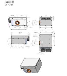
Tank size